 In summary, the Accessory Valet™ wires into your car's power, ground, and
serial data lines and provides an interface to the stock retained accessory
power modes. This allows aftermarket stereos to retain power even after the
key is removed, exactly as the stock stereo did originally.
Description:
In summary, the Accessory Valet™ wires into your car's power, ground, and
serial data lines and provides an interface to the stock retained accessory
power modes. This allows aftermarket stereos to retain power even after the
key is removed, exactly as the stock stereo did originally.
Description:
The Accessory Valet™ module provides retained accessory power
control for aftermarket stereos (head units) and is compatible with many
late model GM vehicles. Please see our website for an updated compatibility
list.
Background:
Many newer GM vehicles have a feature known as "retained accessory
power" or RAP. This feature allows the stereo and select accessories to
operate for some time after the ignition key has been switched off; often
for 10 or 15 minutes, or until a door is opened. Most aftermarket stereo
head units do not support RAP and must be wired into the ignition switch's
ACC signal. This signal allows the aftermarket unit to power-on whenever
the key is in the ON, RUN, or ACC position, but does not allow the stereo
to operate when the key is in the OFF position. As a result, the music
stops as soon as the key is switched off. The Accessory Valet™ decodes
the RAP modes from the digital serial bus and provides a signal to control
the aftermarket head unit, thus restoring the convenience of RAP operation
to aftermarket stereo users.
Usage:
The Accessory Valet™ operates autonomously and tracks your vehicles
RAP modes. It will cause the aftermarket stereo to operate under the same
conditions that the original stock stereo operated. There is no required
input from the driver and no special tricks to remember. Additionally, the
Accessory Valet™ provides a dimmer control output that responds to the
vehicle's headlamp control, allowing the stereo's display to dim at night.
Installation:
The best installation strategy will vary from vehicle to vehicle,
but the required signals should be available at the stock stereo harness.
If you are not comfortable with automotive electrical wiring, any car
stereo or car alarm shop should be able to easily perform the Accessory
Valet™ installation.
Be sure that the battery is disconnected before attempting to wire any new
accessories. An inadvertent short could blow a fuse or cause extreme
heating or melting of metal tools. This can be very dangerous. A ring
or loose jewelry could short and melt causing severe burns.
The Accessory Valet™ requires a constant +12V supply. Be sure this
line is properly fused. The pre-installed fuse inside the Accessory
Valet™ only protects the Accessory Valet™ and its stereo output controls
from shorts, so the main supply line still needs its own fuse.
Be sure that all new wiring is routed to avoid any moving parts, such
as gear shifters and foot pedals, where repetitive motion or vibration
can wear wiring and cause electrical damage or interfere with driver
safety.
Wiretaps are supplied to make connecting the Accessory Valet™ quick
and easy. These connectors are made by 3M and are UL listed. They can
be slipped around an existing wire without having to cut or splice into
it. The side is folded up and snapped closed to hold the main wire in
place. The new connection is made by sliding the end of an unstripped
wire fully into the remaining port and pressing the metal clip with a
pair of pliers until the clip is flush with the plastic body. The lid
snaps closed to insulate the connection.
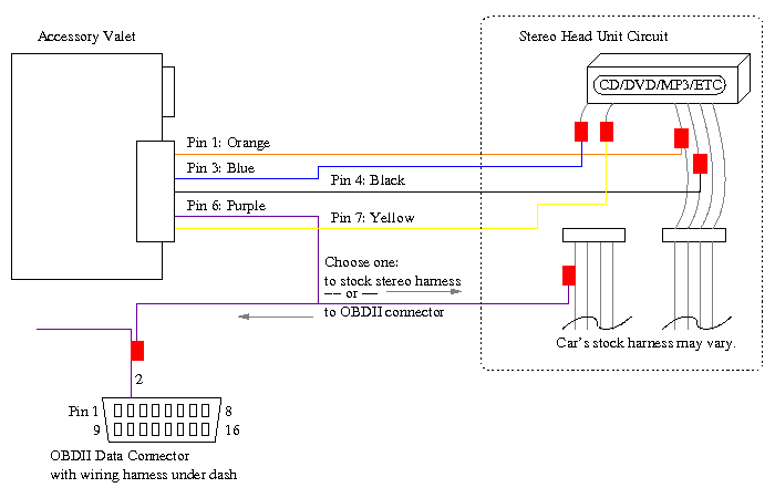
Recommended procedure:
Setups may vary between vehicle models, but the Accessory Valet™
is easy to install with a minimum of only four required connections.
Pin 1 (Orange) should be connected to a fused +12V always on power
source. If connected at the head unit, it should connect to the +12V
signal that is always energized.
Pin 4 (Black) should be connected to a ground lead.
Pin 6 (Purple) is the serial data line. Since the stock stereo
supported the retained accessory power modes, one of its connecting
harnesses had to have the serial data line. Identify it and connect
it to pin 6 (purple) of the Accessory Valet™ wiring harness. (If
you are familiar with the use of a volt-ohm meter, see the
troubleshooting section for a tip on identifying the signal.) If
identification of the serial data line is not possible within the
original stereo harness, the signal can also be found on the OBDII port
at pin 2 just below the edge of the dash trim on the driver's side in
most vehicles. Trace the wiring harness by either removing the necessary
trim panels, or by removing the connector itself. Connect the lead from
pin 2 (probably purple) of the OBDII port to the purple lead of pin 6
of the Accessory Valet™ harness.
Pin 7 (Yellow) should be connected to the lead from the head unit
that is labeled ACCessory. Most head unit installations suggest that
one of its power leads (actually a control signal) be connected to a
lead from the ignition switch that is energized when the key is in the
accessory position. This is where the Accessory Valet™ takes over.
Connect the head unit lead to Pin 7 (yellow) of the Accessory Valet™
harness instead. This lead from the head unit should not be connected
to any other signals and should not be routed to the ignition switch as
directed by the head unit installation instructions. If multiple
devices (such as amps, etc.) are all controlled by the ignition's ACC
line, these may all be disconnected from the ignition switch ACC and
connected to this Accessory Valet™ line instead. This line cannot
provide high current power to accessories; each accessory still requires
its own always energized power supply connection.
Pin 3 (Blue) (optional) should be connected to the lead from the
head unit that's labeled dimmer or illumination. Many head units do
not support this feature, but for those that do, this signal will
indicate when the headlights are on so that the head unit can dim its
display for night time use. This lead should not connect to any other
signals or lamp feeds.
Once all the required connections are made, the battery can be
reconnected so that the system can be tested. To test, verify that the
aftermarket head unit cannot be turned on without first turning on the
key. Then, insert the key and turn the ignition switch to the ACC
position. The aftermarket head unit should have power; verify that it
can be turned on and operates properly. Now, if all doors are closed
and then the ignition key is then switched off, the head unit should
still have operating power. Upon opening a door, the power to the head
unit will be interrupted. Power will also be interrupted when the
vehicle's stock RAP timer expires. This may take 10 or 15 minutes
depending on the vehicle model.
Before completing the installation process and re-installing all
necessary components, find a flat surface to mount the Accessory Valet™
with its double-sided sticky foam. Be sure to clean and dry the surface
so that the foam will make a strong bond. Alternately, the Accessory
Valet™ can be secured with zip-ties to a solid fixture or cable harness.
Be sure that it's clear of any moving parts and will not be in a position
to vibrate or cause an annoying rattle. Enjoy!
Troubleshooting:
Since the Accessory Valet™ only connects to power, ground,
OBDII data, and the head unit's ACC and dimmer leads, any possible
problems will likely be easy to isolate. Here's a few tips on
troubleshooting system issues related to the connections:
- Be sure the battery has been reconnected.
- If the aftermarket head unit cannot be powered up, verify that its ACC line is properly connected to pin 7 of the Accessory Valet™. This line should be over 10 volts when the vehicle's ignition switch is on.
- Verify that the Accessory Valet™ power lead (pin 1, orange)
has a +12V supply that is always on. If the voltage is switched off by
the ignition, the Accessory Valet™ will not be able to control the
aftermarket head unit when the ignition key is off.
- Check that the black ground lead (pin 4) is properly grounded.
- A multi-meter can be used to verify that the Accessory Valet™
has a connection to the OBDII data line. Even if this signal was
connected via the stock stereo's wiring harness, this test will still
be good. With the meter set to volts, connect one lead of the meter to
pin 2 of the OBDII port and the other lead to pin 6 of the Accessory
Valet™ wiring harness. The voltage should read approximately 0
volts. If it reads 0 volts, then it is safe to switch to ohm mode to
read the resistance. The resistance should be approximately 0 ohms (or
less than 10 ohms).
Electrical wiring diagram:
|
|
